

Building the UpX4 Neo 2020
by John Paul Chacha on Mon, 23rd Aug 2021. Read 6438 times.
The old amp from 2011 has served me well for close to 9 years and I was planning to keep it for much longer, which is why I gave it a facelift in 2018. However, as fate would have it, it blew an output (mostly my fault) and as I was taking it apart. I had half a mind to fix it but I thought to myself that instead of replacing the difficult-to-find transistors, I should just build a new amp.
The following is a not-very-in-order account of the build, which was done over the course of several months during the COVID-19 lockdowns in Kenya.
For the new amp, I elected to maximize modularity. In particular, I wanted it to be extremely easy to fix; easy enough that replacing a blown output would be comparable to replacing an expansion card in a desktop computer. To this end, I chose a design where everything built as a separate module with nice plugs and what-not.
Well, I found myself having to remember this stuff out of a need to wind a DIY autotransformer to split a rail into several voltages. I cheated a little, though: there’s a very nice calculator at dicks-website.eu that you can use for this, although it isn't specifically designed for autotransformers.
That went well, initially, but I soon discovered that it wasn't putting out enough current to run everything I needed it to. The internal resistance was simply too high, and I wanted good standby characteristics (specifically low magnetizing current), so really had no choice, I had to start from scratch with a larger core and beefier wire.
I don’t like noisy transformers (who does?) so I embalmed the windings in epoxy, and made proper terminations so that I’ll have the option of easily reusing this is a future project if the need arises.
PS: That final picture is from a later stage in the build).
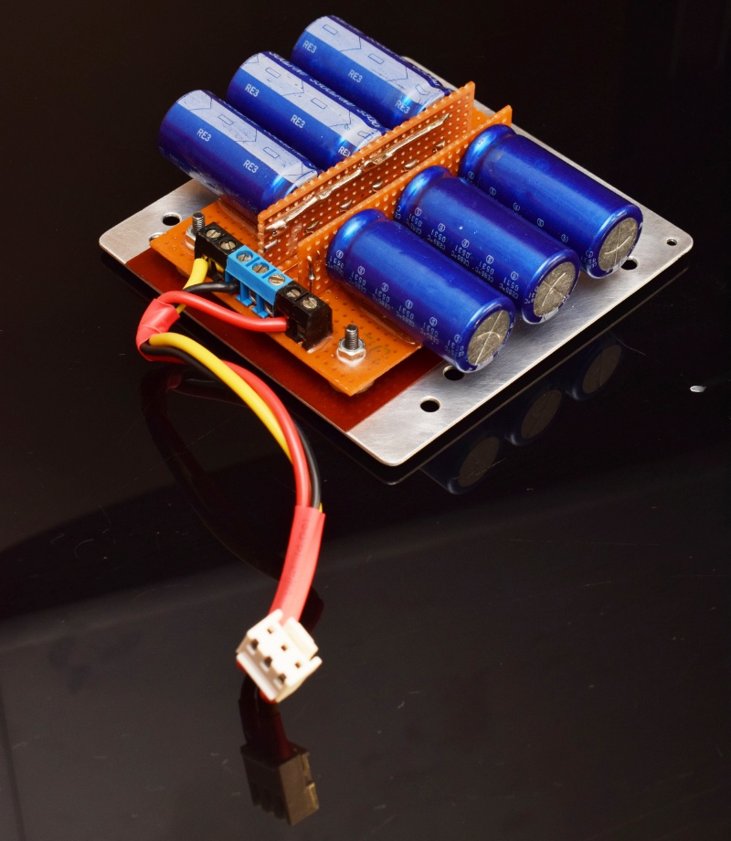
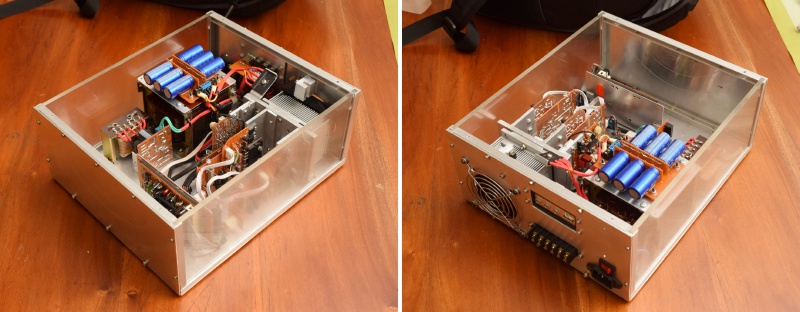
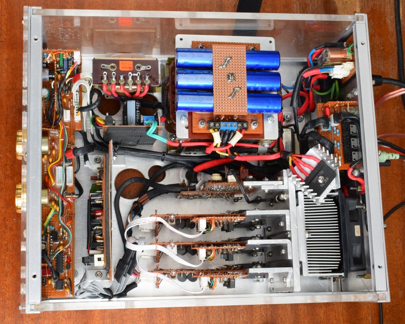
For the main supply, I reused the 7 kilogram 35-0-35 from the old transformer, which, after rectification, gives a rail-to-rail voltage of about 100 volts. For the filter bank, I’ve found that paralleling capacitors tends to work better than using one large capacitor; you get better ESR, better current handling and as a bonus, better space efficiency. Rectification is via a 50-amp bridge rectifier, which will be mounted on its own heatsink which will then be mounted on the main heatsink.
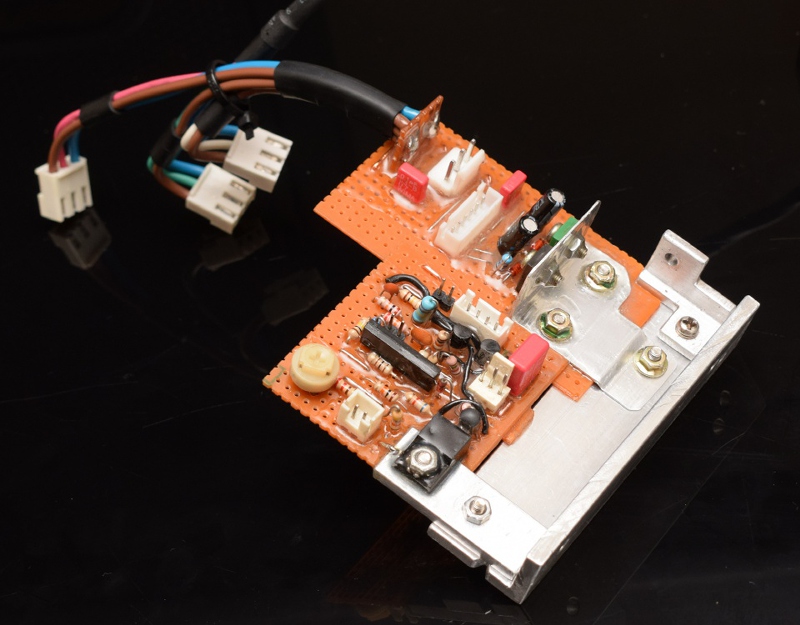
This is the solution I came up with. The sub-module on the bottom-left is the fan control, while the one on the top-right is a power interface module that takes power from the main supply and routes it to the outputs and the core. The core needs two (four?) voltage levels, dual-rails at full voltage and current plus low-current dual-rails at about a third of that with low ripple; this module provides that (the black and green transistors form a dual-rail linear regulator).
PS: Didn’t realize that heat-shrink tubing is not only available locally but is also very reasonably priced. No more untidy wiring.
With that ready, I went on to build the modules themselves. They are technically hot-plug but I don’t intend to use them that way. Each takes 4 outputs, 2 at the front and two behind, and bolts into the shared heatsink via two bolts and two captured nuts. 12 outputs in total, feeding 3 channels (I know; I just love 3-channel amps, and that’s the UpX4 design anyway, so...).
All was going well until I decided to push them to 33% of max load (or was it 20%?) to see how the cooling solution would hold up, at which point I discovered that my very nice Toshiba transistors, which had passed initial testing, were useless counterfeits. Thankfully, I’d designed the modules to be easy to fix.
No more locally-sourced outputs, the replacement batch will be imports and definitely not from China.
By the way, the trick to getting perspex all shiny is rubbing compound and an orbital buffer (or lots of muscle-power), just like with automotive clearcoat.
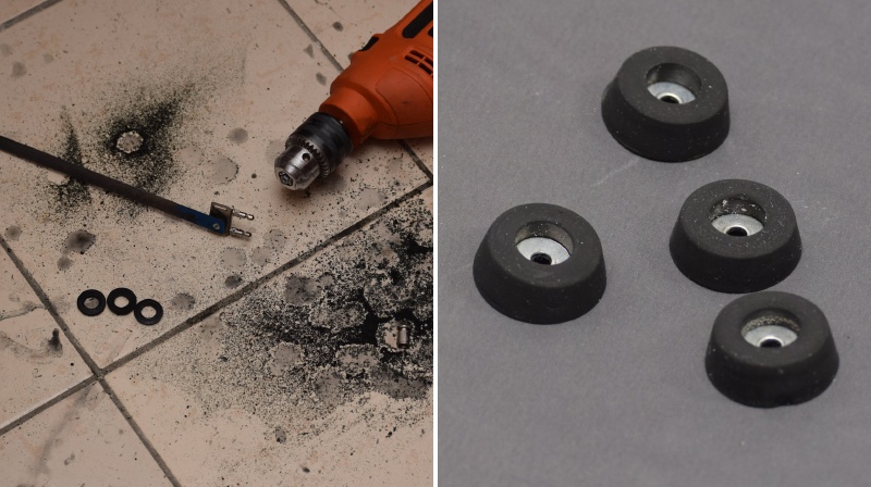
I made custom rubber feet by using a drill as a lathe and a saw blade attached to a flat piece as a trimmer, followed by some high-speed wet-sanding. A washer in the center and a bolt and nut completes the rubber foot. They look good, don’t they?
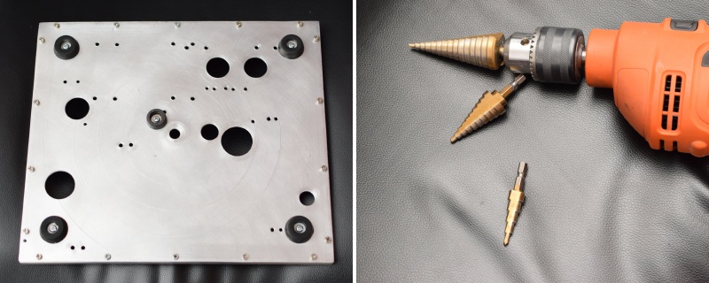
I initially thought of providing cooling vents on the front panel but I couldn’t find a way of making them not look ugly (yes, I tried). I then elected to provide ventilation from below, considering the clearance provided by the rubber feet (there’s also a vent on one of the perspex panels to augment these, by the way). These step-drill bits are a must-have if you intend to work on aluminium. I made these cooling vents in no time at all.
PS: Interesting address, Digi-Key.
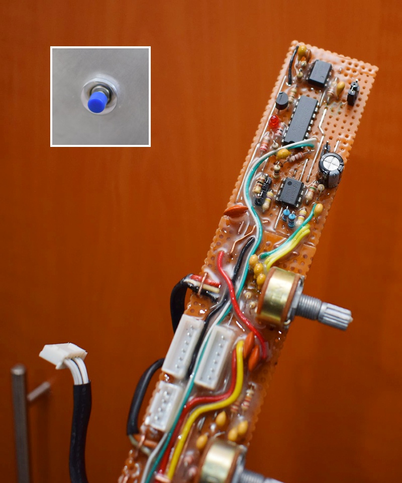
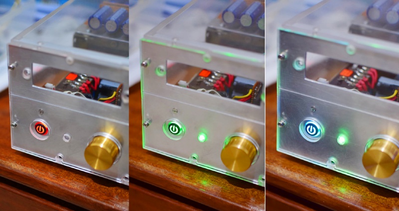
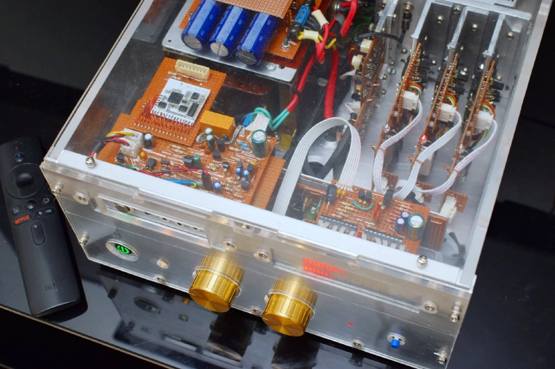
It glows soft-red when amp if off and bright green when powered on; toggles state with single press. Always starts in the "off" state; this is enforced by an RC decay timer incorporated into the circuit.
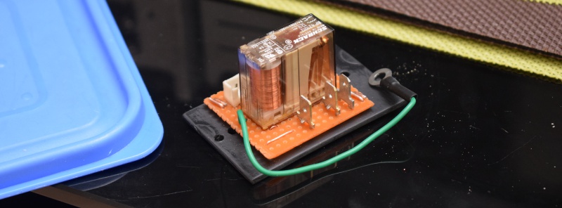
... and this is the mains relay, with a ground wire between the hot and cold sides for extra safety. Speaking of grounding, the mains earth and signal ground are separated and isolated, so no ground-loop issues ...
... and here’s the stand-by transformer I menttioned earlier. I chose a very low VA unit to minimize magnetizing current (and therefore standby consumption) because this will remain powered as long as the amplifier is on stand-by. When switch on, the relay cuts this off and connects the main transformer, so only one of them is connected to mains at any one time. Generously epoxied, as usual ...
We live in a world where conservation is important, and amps take quite a bit of power even if there’s no sound playing (and this build is a notable offender in this regard because it is configured for high-bias to maximize sound quality). My solution is to switch off the amp automatically after a preconfigured amount of time if there’s no signal. However, since it’s a bit disconcerting for it to just suddenly go off on you, it will warn you first. So, the power button now behaves this way:
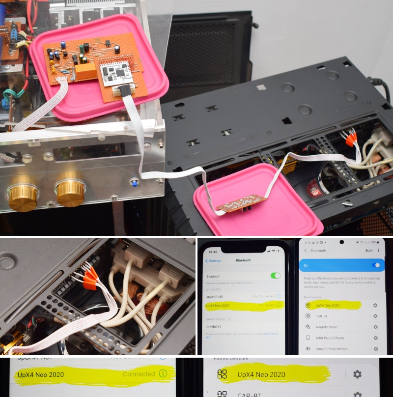
Computers don’t have SPI ports so my homebrew SPI-to-LPT converter was needed together with some software that can “bit-bang” a parallel port. We can connect to two devices simultaneously, by the way.
In English:
I’m adding the bluetooth audio capability to the amp, but I need to program the bluetooth module first (set name, configs, etc.). That has to be done via a computer, but the module uses an interface that is common in the world of embedded devices but nonexistent in the world of personal computers – Serial Peripheral Interface, or SPI for short. There is, however, a way to simulate an SPI interface using a Parallel port by (1) building a circuit to adapt the voltage levels and (2) using software to directly manipulate the signals on the parallel port; this is called bit-banging. This is only possible on DOS and 32-bit Windows, 64-bit Windows doesn't allow such direct manipulation.
The bluetooth module is configured allow connection to two devices at the same time, although music can only be set by one device at any one time.
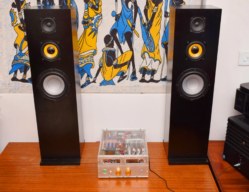
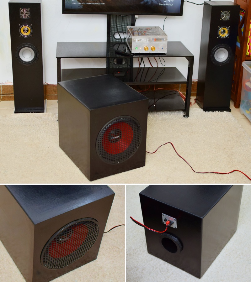
The tower enclosures are by my brother, by the way. The subwoofer that goes with them is still work in progress, as is the bluetooth module for the amp (hence the holes). VU meter is complete, but I’m still not sure I want it there.
PS: Yes, colours of the year 2021 ...
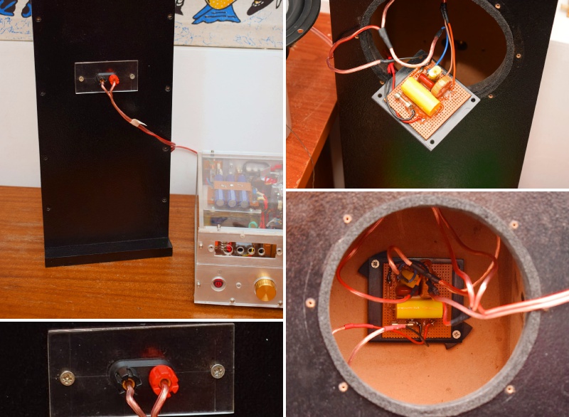
The cabinets, for both the towers and the sub, are by my brother – he’s very good at doing speaker enclosures, so I elected to outsource that bit to the expert.
PS: I added grilles coz of the kids.
The old amp from 2011 has served me well for close to 9 years and I was planning to keep it for much longer, which is why I gave it a facelift in 2018. However, as fate would have it, it blew an output (mostly my fault) and as I was taking it apart. I had half a mind to fix it but I thought to myself that instead of replacing the difficult-to-find transistors, I should just build a new amp.
The following is a not-very-in-order account of the build, which was done over the course of several months during the COVID-19 lockdowns in Kenya.
For the new amp, I elected to maximize modularity. In particular, I wanted it to be extremely easy to fix; easy enough that replacing a blown output would be comparable to replacing an expansion card in a desktop computer. To this end, I chose a design where everything built as a separate module with nice plugs and what-not.
Custom Autotransformer, Main supply
Everyone remembers turns-ratio, but how many of you remember how to calculate Fmax (maximum magnetic flux), �e (effective permeability) and Ae (effective cross-section) for a given core and use that to determine the minimum number of primary turns required to meet your desired performance characteristics?Well, I found myself having to remember this stuff out of a need to wind a DIY autotransformer to split a rail into several voltages. I cheated a little, though: there’s a very nice calculator at dicks-website.eu that you can use for this, although it isn't specifically designed for autotransformers.
![]()
That went well, initially, but I soon discovered that it wasn't putting out enough current to run everything I needed it to. The internal resistance was simply too high, and I wanted good standby characteristics (specifically low magnetizing current), so really had no choice, I had to start from scratch with a larger core and beefier wire.
I don’t like noisy transformers (who does?) so I embalmed the windings in epoxy, and made proper terminations so that I’ll have the option of easily reusing this is a future project if the need arises.
PS: That final picture is from a later stage in the build).
![]()
![]()
![]()
For the main supply, I reused the 7 kilogram 35-0-35 from the old transformer, which, after rectification, gives a rail-to-rail voltage of about 100 volts. For the filter bank, I’ve found that paralleling capacitors tends to work better than using one large capacitor; you get better ESR, better current handling and as a bonus, better space efficiency. Rectification is via a 50-amp bridge rectifier, which will be mounted on its own heatsink which will then be mounted on the main heatsink.
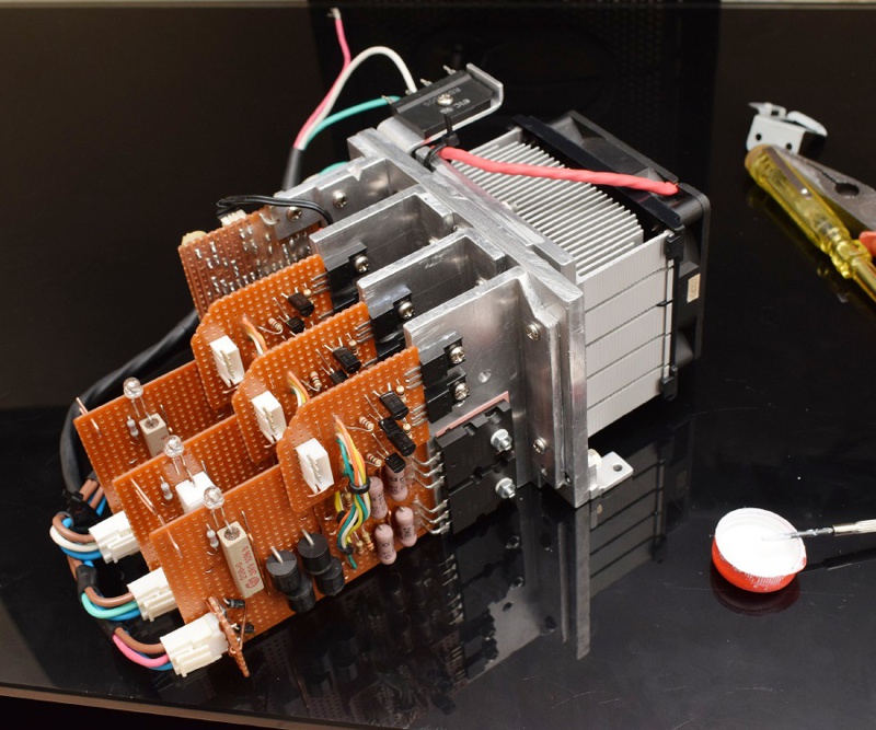
Fan control module, power interface module
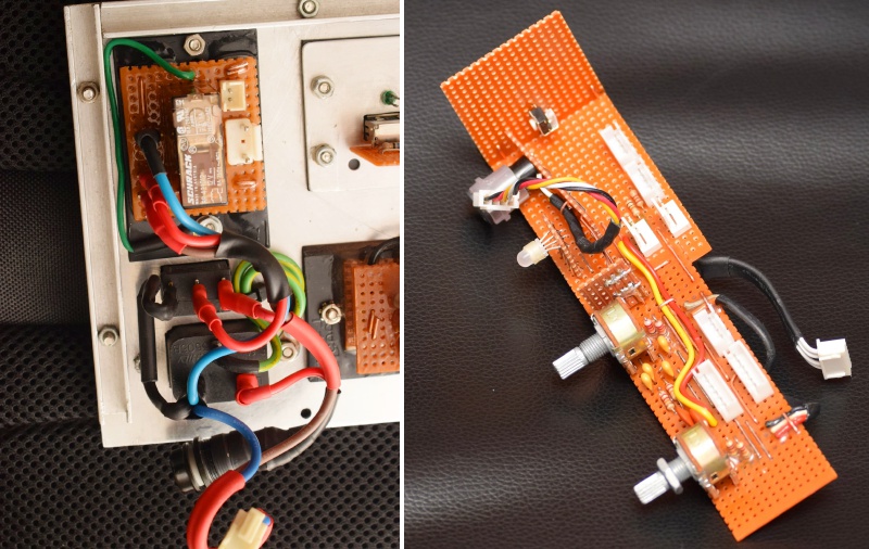
Fans can get noisy at full speed, so you want to be able to control fan speed based on temperature. However, simply changing the fan voltage with temperature won’t cut it coz fans have a stall speed. Also, you want some hysteresis in the control loop to avoid the whole thing turning into an oscillator, and you want to avoid driving the fan too hard. Finally, you want to know when you’ve reached the end of your control envelop so that you can tell the rest of the system that you’re in the red.This is the solution I came up with. The sub-module on the bottom-left is the fan control, while the one on the top-right is a power interface module that takes power from the main supply and routes it to the outputs and the core. The core needs two (four?) voltage levels, dual-rails at full voltage and current plus low-current dual-rails at about a third of that with low ripple; this module provides that (the black and green transistors form a dual-rail linear regulator).
PS: Didn’t realize that heat-shrink tubing is not only available locally but is also very reasonably priced. No more untidy wiring.
Updated Core
I decided to reuse my trusted UpX4 Core (probably one of the best things I’ve ever designed and built in the name of DIY-audio), albeit with some updates... the only reason why I’d ever need to replace this is if I wanted more channels or if I needed to switch to a completely different topology, otherwise it still suffices.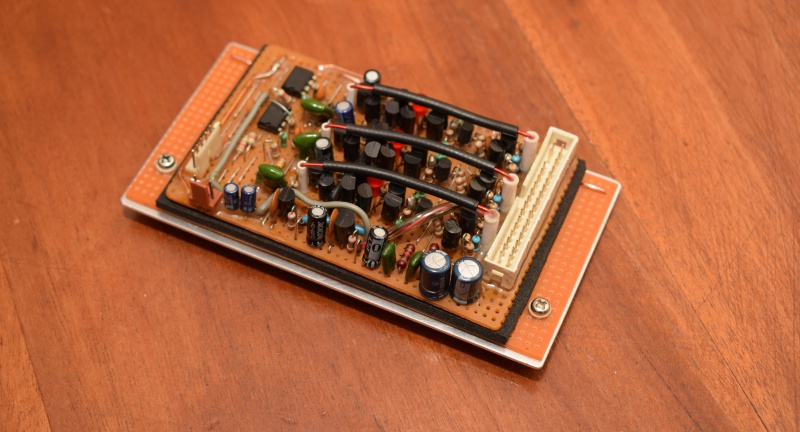
Output modules
Building outputs always starts with some metalwork, naturally; heat dissipation is everything. I still had some of that nice thick aluminium left over so I cut that for the heat-sink base. To make if easy to replace modules (modularity, remember), I embedded nuts into it so that replacement is a screwdriver-only affair ...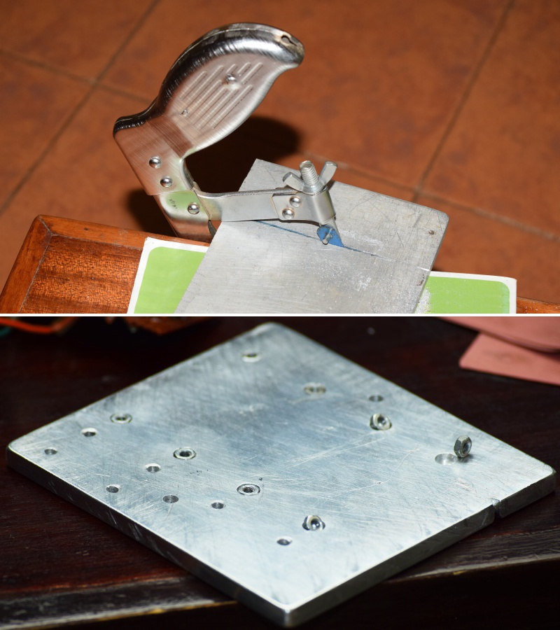
With that ready, I went on to build the modules themselves. They are technically hot-plug but I don’t intend to use them that way. Each takes 4 outputs, 2 at the front and two behind, and bolts into the shared heatsink via two bolts and two captured nuts. 12 outputs in total, feeding 3 channels (I know; I just love 3-channel amps, and that’s the UpX4 design anyway, so...).
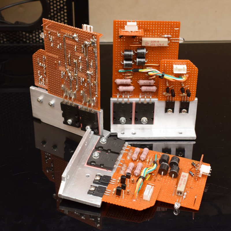
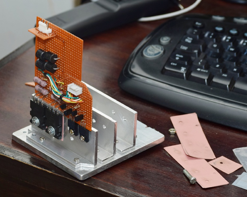
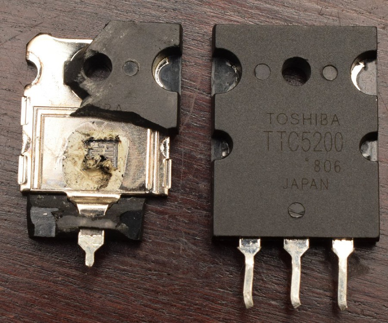
All was going well until I decided to push them to 33% of max load (or was it 20%?) to see how the cooling solution would hold up, at which point I discovered that my very nice Toshiba transistors, which had passed initial testing, were useless counterfeits. Thankfully, I’d designed the modules to be easy to fix.
No more locally-sourced outputs, the replacement batch will be imports and definitely not from China.
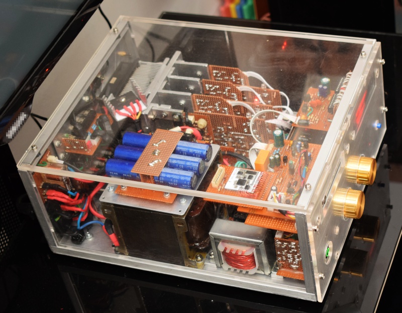
Casing, part #1
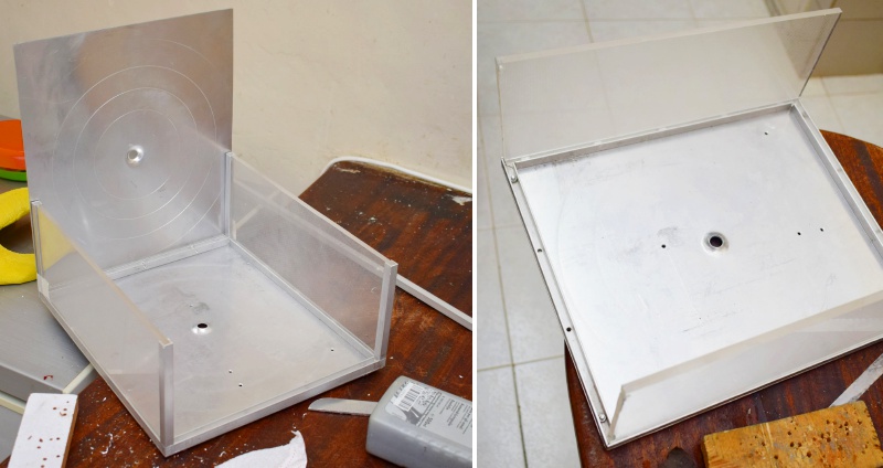
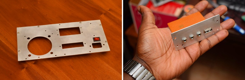
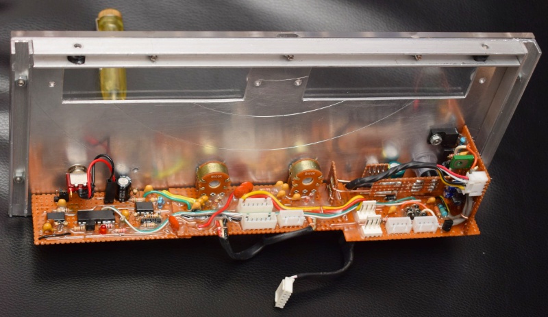
While I was waiting for the replacement transistor, I decided to get started with the casing, so this is fashioning the casing out of aluminium and perspex, part one. Raw materials were two aluminium plastering hawks, an aluminium U-bar and perspex salvaged from the diffusers of two dead computer monitors. In case you’re wondering, the USB port is for powering a portable signal source attached to the amp, such as a tablet computer or smart-phone (this is part of the reason why I needed a beefier autotransformer).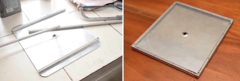
By the way, the trick to getting perspex all shiny is rubbing compound and an orbital buffer (or lots of muscle-power), just like with automotive clearcoat.
I made custom rubber feet by using a drill as a lathe and a saw blade attached to a flat piece as a trimmer, followed by some high-speed wet-sanding. A washer in the center and a bolt and nut completes the rubber foot. They look good, don’t they?
I initially thought of providing cooling vents on the front panel but I couldn’t find a way of making them not look ugly (yes, I tried). I then elected to provide ventilation from below, considering the clearance provided by the rubber feet (there’s also a vent on one of the perspex panels to augment these, by the way). These step-drill bits are a must-have if you intend to work on aluminium. I made these cooling vents in no time at all.
Transistors with manners
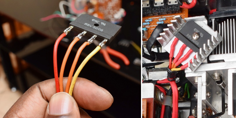
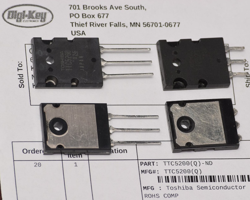
Haya, the transistors are here so the build can continue. Apparently, importing from places that care about reputation is the only way to get genuine power transistors. Here’s a comparison of the genuine imports vs the Chinese counterfeits sourced locally; they come close, but there are differences (fakes are the ones with clipped leads/pins).PS: Interesting address, Digi-Key.
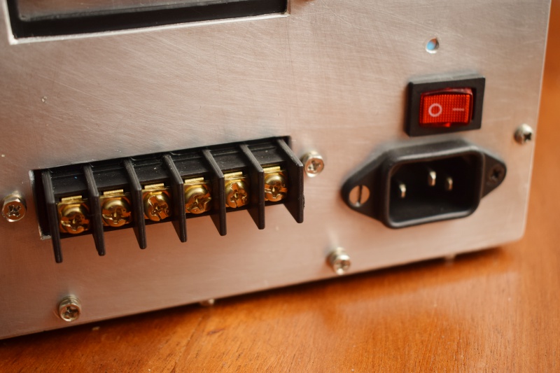
Power-switch module, front panel
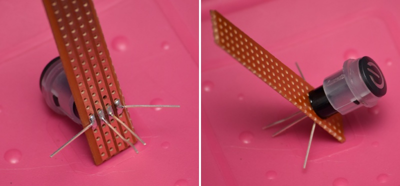
This is 2020, I am not going to run live wires to the front for a mains switch. Instead, I elected to build a dual-colour (later upgraded to triple-colour) backlit soft on/off button; it works in conjunction with a mains relay and stand-by transformer in the back panel (yes, transformer number three). Built from the ground up by hand with discrete components. The button cover was sourced from a dead printer, cut and filed to size, after which I threw an RGB LED in there and found a similarly sized piece of plastic to hold the LED in.It glows soft-red when amp if off and bright green when powered on; toggles state with single press. Always starts in the "off" state; this is enforced by an RC decay timer incorporated into the circuit.
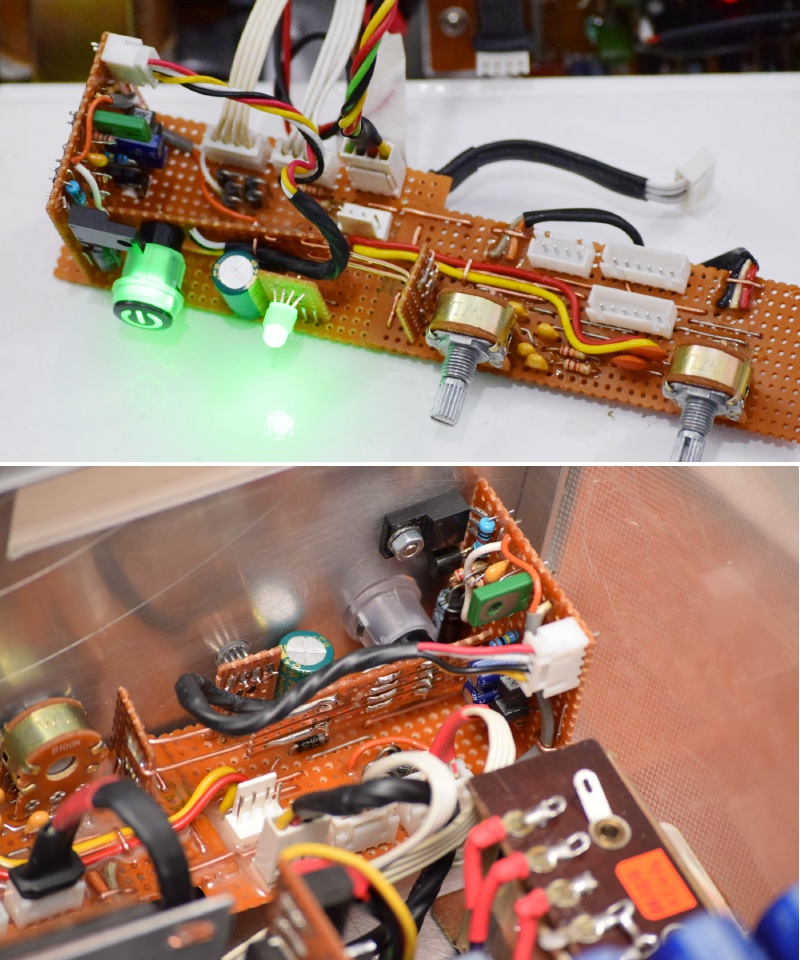
... and this is the mains relay, with a ground wire between the hot and cold sides for extra safety. Speaking of grounding, the mains earth and signal ground are separated and isolated, so no ground-loop issues ...
... and here’s the stand-by transformer I menttioned earlier. I chose a very low VA unit to minimize magnetizing current (and therefore standby consumption) because this will remain powered as long as the amplifier is on stand-by. When switch on, the relay cuts this off and connects the main transformer, so only one of them is connected to mains at any one time. Generously epoxied, as usual ...
![]()
![]()
Going digital
Let’s add some digital electronics to the mix ... these are going into the front panel. So, what was I up to? I was adding a signal detector, a pulse generator, a digital counter and a third color for the power button LED, namely cyan (sky-blue). What for, you ask?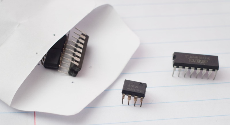
We live in a world where conservation is important, and amps take quite a bit of power even if there’s no sound playing (and this build is a notable offender in this regard because it is configured for high-bias to maximize sound quality). My solution is to switch off the amp automatically after a preconfigured amount of time if there’s no signal. However, since it’s a bit disconcerting for it to just suddenly go off on you, it will warn you first. So, the power button now behaves this way:
- RED: Amp is off, everything is powered off except the small standby transformer that powers the LED and the power switch circuitry. Pressing the power button will switch the amp on.
- GREEN: Amp is on. The pulse generator and digital counter start counting the seconds. If a signal is detected, the counter goes back to zero. If no signal is detected for a preconfigured time, the LED changes to blue.
- BLUE: Counting continues. If a signal is detected, we go back to green. The same thing happens if the reset button is pressed. If a preconfigured time elapses without a signal being detected, the amp is switched off and we go back to red (standby).
Bluetooth module programming
I’m calling it UpX4 Neo 2020.Computers don’t have SPI ports so my homebrew SPI-to-LPT converter was needed together with some software that can “bit-bang” a parallel port. We can connect to two devices simultaneously, by the way.
In English:
I’m adding the bluetooth audio capability to the amp, but I need to program the bluetooth module first (set name, configs, etc.). That has to be done via a computer, but the module uses an interface that is common in the world of embedded devices but nonexistent in the world of personal computers – Serial Peripheral Interface, or SPI for short. There is, however, a way to simulate an SPI interface using a Parallel port by (1) building a circuit to adapt the voltage levels and (2) using software to directly manipulate the signals on the parallel port; this is called bit-banging. This is only possible on DOS and 32-bit Windows, 64-bit Windows doesn't allow such direct manipulation.
The bluetooth module is configured allow connection to two devices at the same time, although music can only be set by one device at any one time.
Final touches (after a break)
In case you’ve been wondering, no, the project didn’t stop, but I slowed down a bit to attend to other things.The tower enclosures are by my brother, by the way. The subwoofer that goes with them is still work in progress, as is the bluetooth module for the amp (hence the holes). VU meter is complete, but I’m still not sure I want it there.
PS: Yes, colours of the year 2021 ...
Final touches (after another break)
Went underground a bit (got busy with other things) but the project didn’t stop. Subwoofer is here and I finished building the Bluetooth and VU meter modules (although I prefer a wired connection for obvious reasons).The cabinets, for both the towers and the sub, are by my brother – he’s very good at doing speaker enclosures, so I elected to outsource that bit to the expert.
PS: I added grilles coz of the kids.

Quick Links
Popular Articles
Other Content
Donations
Did you like the article?
Kindly make a donation via PayPal to keep the projects going.
Kindly make a donation via PayPal to keep the projects going.